Grand Master
I had been meaning to do a vision and robotics project for a while now and thought it would be fun to make a robot play chess. The core objectives of this project was to implement a vision based system that used a 3D printer to play chess. Ideally, this solution would have used a delta robot however the delta robot I am working on is still in its very early stages of development. Another objective was to ensure the vision solution was independent of the camera and chess board location or orientation. The implication here is that the camera can be loosely attached over the 3D printer with no expectation that the camera is anywhere in real world space. There is one minor exception to this: the camera has to have the board and the printing tray in it’s field of view. The main skill sets that this project implements is 2D vision, robot command, dynamic path targeting, and multi process/hardware communication.
Implemented Technology
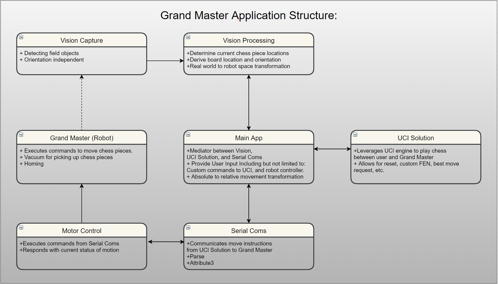
This project used a simple fiducial tracking approach to derive the chess board location and orientation relative to the platform. The platform fiducials are reference locations which are assumed to be stationary. This allows for the transformation from vision space to robot space and vice versa. A user move request is made through the application’s user interface chess board or by selecting “Auto Move”. This move request is sent from the Main App over a named pipe to the UCI ( universal chess interface ) Solution. See the diagram below. If you are unfamiliar with named pipes, they are just another way to communicate between different processes. The UCI solution acts as a chat client that wraps a c++ UCI engine library. For a valid move (or get best move) request, the Main App is returned a string with the UCI formatted move string to be performed. An example of a UCI format move string could be “B2B4”. Given a UCI move string, the Main App gets the ideal robot space locations and then sends these ideal robot space location over another named pipe to the vision application to determine if a valid frame is active. If there is no valid active frame the application waits until one becomes available. This frame is used to transform the ideal points to the actual target location thus allowing for “dynamic” targeting of an object on the chess board. Below is a birds eye view of the applications structure.

Things To Lookout For
The MakerBot is not a cartesian robot in the sense that the X and Y axis are not controlled independently. In this case, the Z axis is independent and easily controllable by one motor. However, the X axis (set to be an end effector movement towards the back of the printer) requires a negative rotation of one motor and a positive rotation on another motor. Similarly, the Y Axis (set to be an end effector movement towards the left of the printer) requires that both the second and third motor have a negative rotation. To accommodate for this, the robot controller was not able to use absolute paths. Instead an interpolated path was created in the currently selected robot space frame. From this, a dependent XYZ command was required to hit the target location.
It is worth noting that the XYZ axis that were selected for the robot are arbitrary and the only constraint that really needed to be considered was not violated the right hand rule. For example, you can set the X axis to any vector in 3D space. The Y can then be any vector that lands on the plane that is normal to X. However once X and Y are established, Z is simply the cross product of X and Y. While that is the only constraint that must be followed one thing that I would do in the future is to ensure that the axis I selected for the robot was easier to transform to the vision system axis. By this I mean, on the vision processing side, the X axis of the image was considered along the width from left to right and the Y axis along the height from top to bottom. This puts the z axis into the image. The reason I bring that up is because when the robot moves along the image positive X it is moving along the negative Y in robot space. Additionally, when the robot is moving along the image positive Y it is moving along the negative X in robot space. This ended up requiring otherwise unnecessary complexity to this particular application. The solution becomes much cleaner to read, and debug when you switch to axis that do not require axis flipping.
Lighting is everything. In this solution I went with colored fiducials for fiducial tracking. While colored fiducials are simpler in many ways than grey scale it did introduce other issues. There was a fair amount of effort needed to ensure proper color fiducial tracking. With that said, performance would have increased with a better camera. In the future I would not rely on colored fiducials. Instead I would stick with grey scale image processing and include more fiducials. Proper fiducial tracking can easily be accomplished with minimal environmental constraints. To add to this, better accuracy could be accomplished with more fiducials because it would allow for better 3D camera location/orientation interpolation thus allowing for more accurate accounting for perspective warping caused by scaling from perceived changes of fiducial spacing. Lastly, additionally fiducials would allow for better tracking related to occlusion, noise canceling and add stability to any plane derivations.
Room For Improvement
The application is dynamic however it is based on a snap shot in time. This is important because any movement of the chess board after a move command would not be accounted for resulting in a target miss. This could be minimized by adding a safety curtain that would determine if a safety zone was violated. After a space violation, the system would need to reregister the targets location. However, this would still not be truly dynamic tracking. Alternatively, truly dynamic targeting could happen however an additional non overhead vision solution would need to be implemented. This is because the field of view would be heavily occluded as the robot enters the field of view. Knowing where you are, where you are going and a snapshot of the field of view at the time of command you can interpolate the relative location and orientation of the target. While, it is not necessarily required to know where you are and where you are going it would help speed up the processing time by limiting the search area. The addition of another camera would allow for more dynamic target location. With that said, I believe they call that feature creep and would be a bit overkill for the version 1.0.
I mentioned earlier that the camera position and orientation is not known. This is true to some extent however the current application does not account for large deviations relative to the camera plane and the platform plane being parallel. As mentioned earlier one approach to solve this would be to add additional fiducials to account for perspective warping.
The actuation of the electro magnet often caused two problems. First, after the robot reached the drop off location the “chess piece” would not release after the electro magnet was deactivated. This was minimized by creating a small separation between the electro magnet and the metal “chess piece”. Second, with or without the isolating plastic being used the “chess piece” was susceptible to shifting off center when the electro magnet was activated. This gave the impression that the target was not properly located after being dropped off even when it interpolated target point locations where properly derived. One simple solution, that I have not implemented at this time, would be to add centering cone that would prevent off axis shifting when the electro magnet is charged.
- Windowed averaging of the fiducial location and outlier elimination would provide for better noise canceling. While this would introduce some latency in the system it prevents one invalid fiducial frame from causing large instabilities in the derived target location.
